Saturday, October 24, 2026
* All product/brand names, logos, and trademarks are property of their respective owners.
Precision rotating shafts are the quiet backbone of motors, gearboxes, robotic drives, automotive actuators, and power transmission assemblies. Even minor errors in machining can trigger excessive vibration, noise, seal failure, and shortened component lifespan. For design and procurement teams, understanding which process controls separate reliable shaft production from problematic batches is essential when sourcing custom machined rotary components.
Many engineers focus only on final tolerance values listed on drawings, while overlooking the sequence of machining decisions that ultimately decide whether a shaft performs consistently in high-speed service. CNC turning and mill-turn machining workflows for rotating shafts are built around one core goal: preserving stable concentricity, straightness and controlled surface finish through every production stage.

Before any cutting begins, a competent machining partner carries out a full design for manufacturability review. This step checks datum selection, tolerance stacking, surface roughness requirements and material suitability for the intended rotating duty.
For stainless steel, titanium and long slender shaft designs, this is where experienced machinists flag hidden risks: over-specified tolerances that inflate cost, poor datum selection that makes runout hard to hold, or material grades prone to work hardening. Raw bar stock is cross-checked against material test certificates, with spectroscopic verification available for traceability-critical industrial and automotive applications. Blanks are cut with extra stock reserved for gripping, centre hole creation and finishing passes.

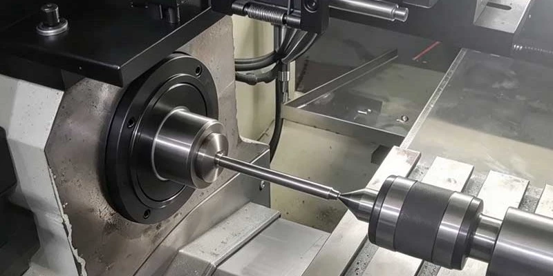
Single-setup mill-turn machining is the gold standard for precision rotating shafts. Every time a component is removed and re-clamped, new positioning error is introduced.

Rough turning removes the bulk of excess material and forms the basic shaft profile. Generous, uniform finishing stock is left on all functional bearing journals, seal lands and shoulder faces.
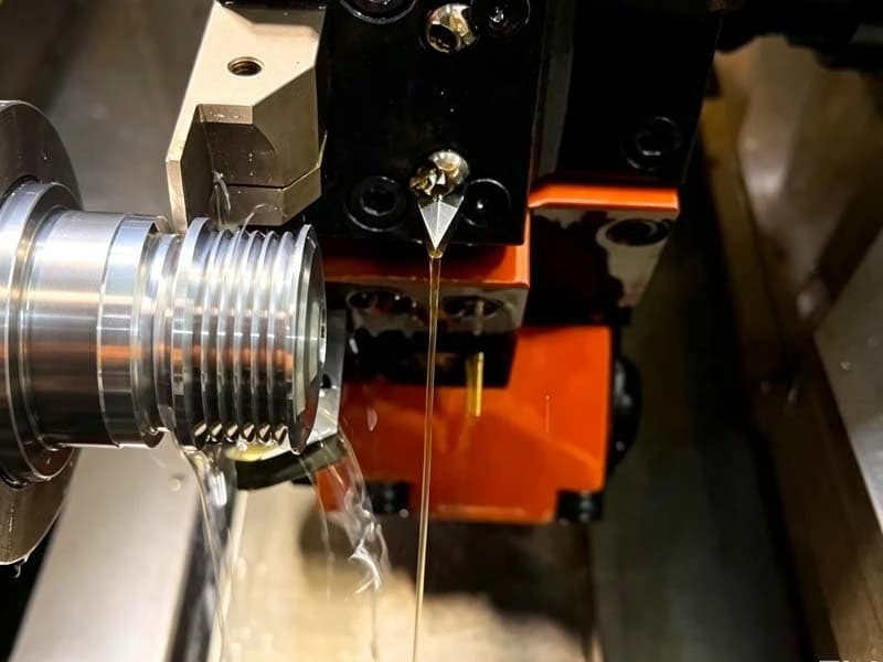
Cutting parameters are tuned to manage heat generation rather than maximising removal speed. Heat and clamping stress locked into the workpiece during roughing will release after unclamping, causing the shaft to bend. That is why slender stainless steel shafts usually go through stress relief after roughing. This controlled thermal cycle releases internal residual stress before semi-finishing, eliminating post-machining springback. Skipping stress relief is a common shortcut used by low-cost suppliers, which leads to high reject rates once parts are assembled.

All interrupted cutting operations are completed before final finish turning. This is a vital sequencing rule. Milling keyways, flats, cross holes, snap-ring grooves, knurling and splines creates vibration and surface hardening. If these operations are carried out after fine finishing, they can distort the precision ground or turned bearing surfaces and introduce dimensional drift.
Mill-turn live tooling completes these non-circular features in the same setup where possible, maintaining alignment with the primary rotational datum.
Finishing is where critical dimensional and geometric tolerances are locked in. Light depths of cut and controlled feed rates minimise cutting forces. Functional mating surfaces for bearings and seals receive a clean spring cut to eliminate feed marks and deliver the required Ra surface finish.
Where drawings demand ultra-smooth sealing surfaces or exceptionally tight runout, secondary cylindrical grinding can be added after turning. Where re-fixturing cannot be avoided, custom locating jigs reference the pre-machined master datum rather than gripping unprepared stock.
Sharp edges on threads, keyways and grooves are removed. Burrs left on rotating components can break free during operation, damage seals and bearings, or create stress risers that shorten fatigue life.
Surface treatments are selected based on material and operating environment: passivation or electropolishing for stainless steel, anodising for aluminium, and plating or black oxide for carbon steel.
Inspection follows a structured multi-stage routine: first article validation, in-process patrol checks, and final verification. Measuring equipment includes micrometers, dial indicators, surface roughness testers and CMM for formal geometric dimension reporting. Measurement data is tracked via SPC to spot batch drift before non-conforming parts are produced. Material certificates and inspection reports can be packaged with shipments for regulated industrial supply chains.
A rotating shaft is only as reliable as the process that made it. Tight tolerances on paper mean little if the machining sequence introduces hidden stress, re-clamping error or uncontrolled heat distortion. The best custom shaft manufacturers treat concentricity and straightness as process targets, not just end-of-line checks.
For teams sourcing custom rotary transmission parts, working with a machining specialist that follows this structured mill-turn workflow reduces assembly issues, cuts field failures and delivers predictable quality across prototypes and high-volume runs. If you need custom CNC rotating shafts built around these process principles, you can explore the precision machining service from Yifeng Metal.

The American apparel market thrives on individuality, premium quality, and brand identity. From
26 September 2026
When engineering teams request CNC quotations, many are surprised by the gap between budget and fina
9 September 2026
Be the first to share your thoughts
No comments yet. Be the first to comment!
Share your thoughts and join the discussion below.